Lift Drawings
Browse lift drawings in PDF and DWG for Aritco home lift and platform lift models. Review dimensions, compare layouts, and access planning files for residential or commercial projects.
Find the Right Lift Drawing Faster
Select a model below to access technical drawings, dimensions, and downloadable files directly.
How to Read Lift Drawings?
Understanding the main dimensions helps you evaluate fit, circulation, and installation requirements before selecting a lift model.
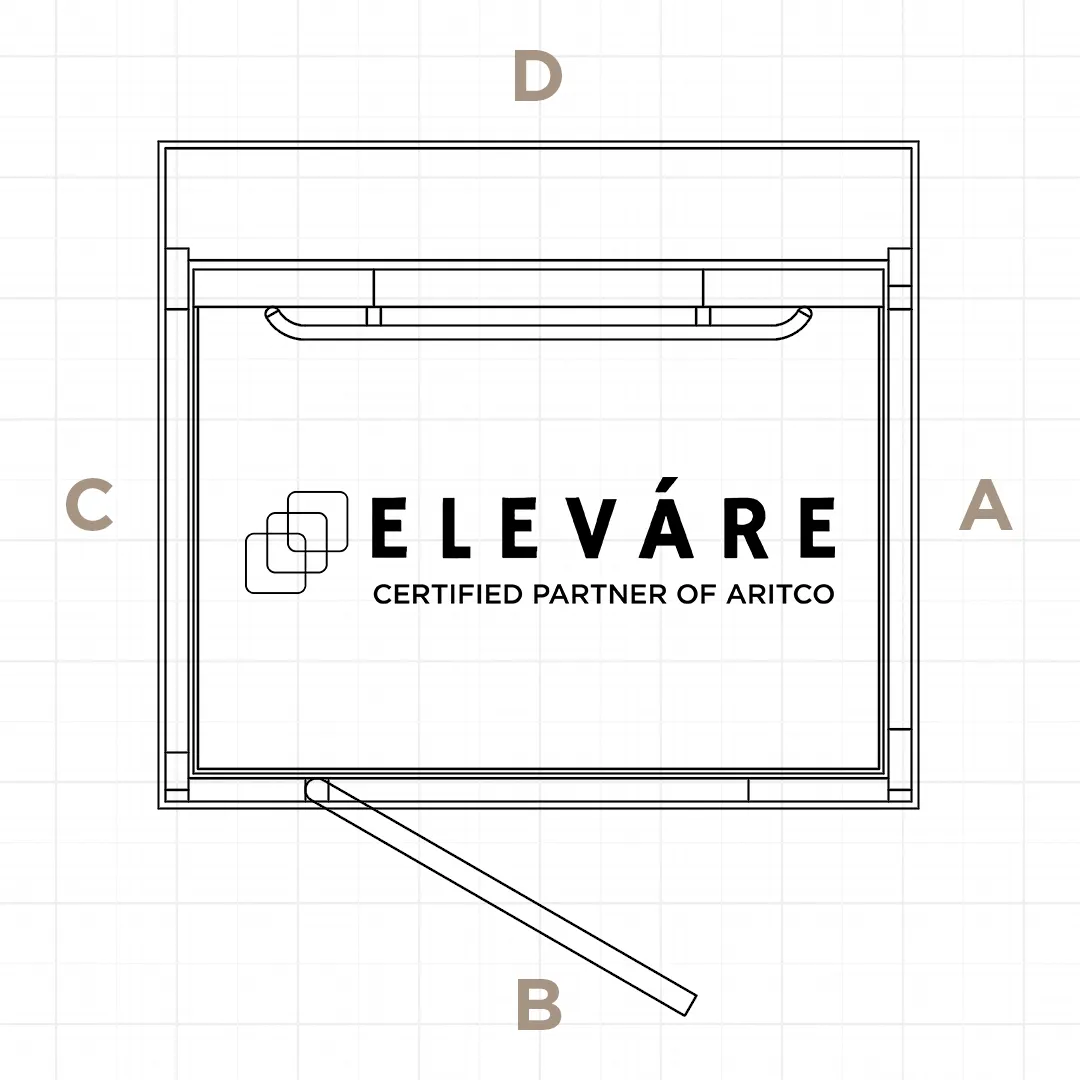
Lift Sides: A, B, C, D
Every Aritco lift has four sides (labeled A–D) which serve as reference points for door configuration and access orientation.
- Side A / C / B: can be fitted with a single door
- Combination of Side A and C: for open-through door configuration
- L-shaped configuration (B + C or A + B): for corner entry solutions
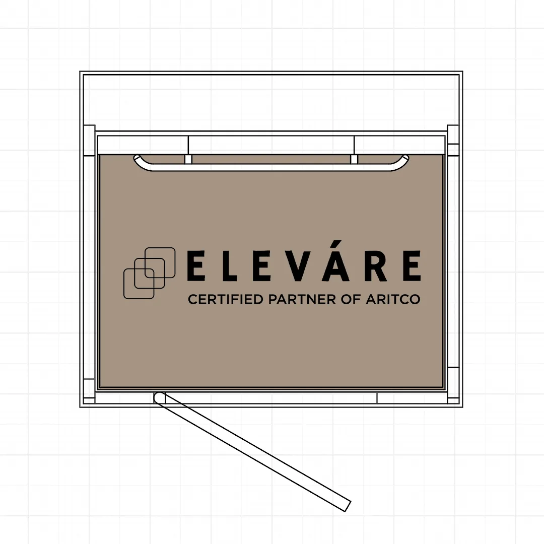
Platform Size
The platform size — highlighted in brown — represents the standing area inside the lift used by the passenger. This is the clear usable space within the lift cabin.
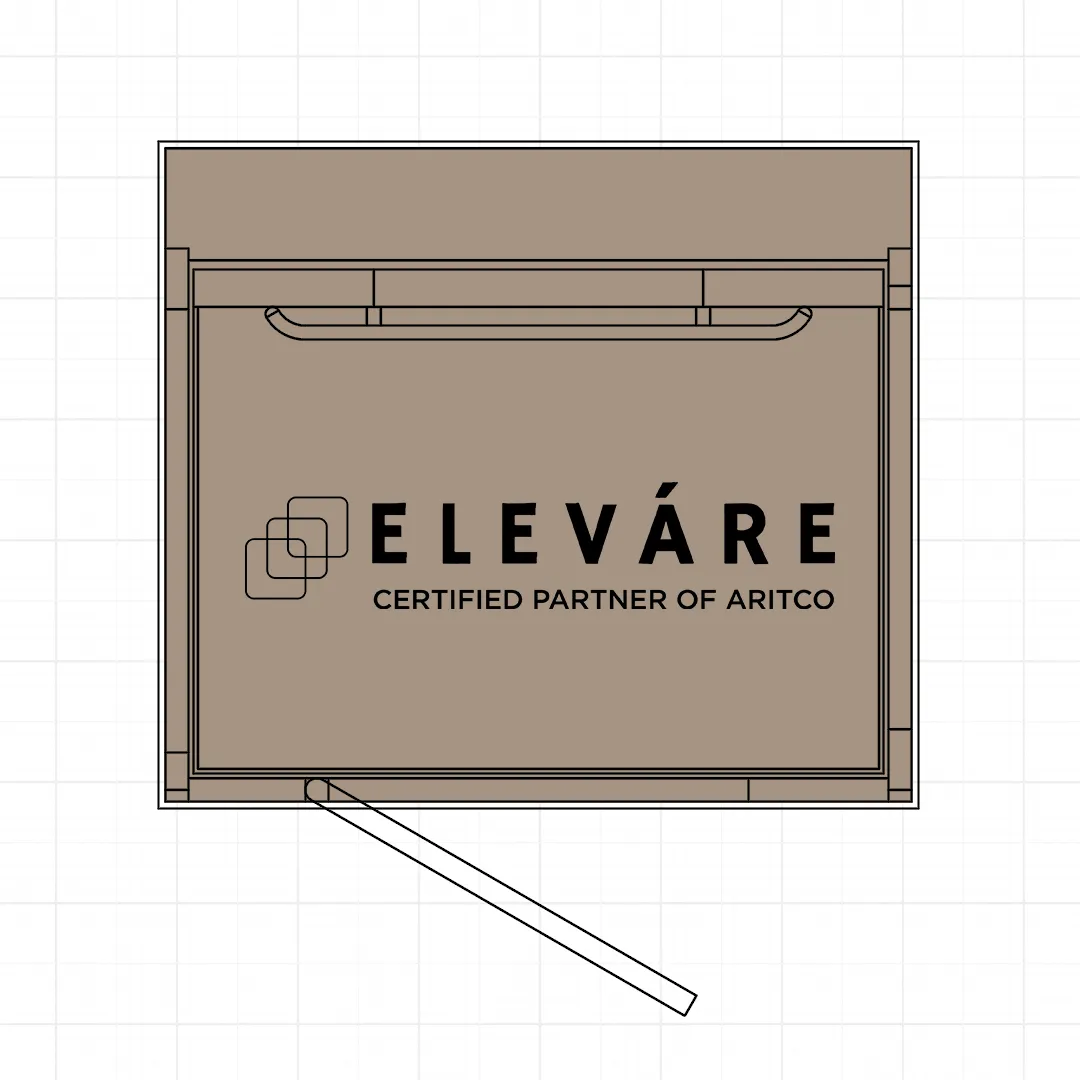
Shaft Size
The shaft size refers to the total clear dimensions of the lift shaft — the full width and depth measured from wall to wall. This includes the lift platform, surrounding safety clearance, and structural space required for installation.
Hole-through Size
This measurement indicates the floor opening (void) required between levels to accommodate the lift shaft and allow proper installation. Ensure that your building’s structure provides sufficient clearance for this space.
Aritco HomeLift Access
Download technical drawings for the Aritco HomeLift Access, developed for higher accessibility needs.
Aritco Lift Public
Download drawings for the Aritco Lift Public, easy accessibility solution for commercial & public buildings.
More Planning Resources
If you are comparing layouts, technical requirements, or client options, these resources can support your planning process.
Need Help Choosing the Right Drawing?
Our team can help match lift drawings with available space & your project requirements.